GEOTECHNICAL ENGINEERING
MEMPHIS
HomeGeophysicsSeismic tomography (refraction/reflection)

Seismic Tomography (Refraction & Reflection) for Site Characterization in Memphis

Technical studies that support your project.

LEARN MORE

The Mississippi Embayment defines subsurface conditions across Memphis, with the Memphis Sand aquifer overlying thick sequences of Tertiary clays and the Paleozoic bedrock surface dropping to depths exceeding 800 feet in some areas. This sedimentary architecture creates distinct velocity contrasts that seismic tomography methods resolve with precision. The New Madrid seismic zone, centered roughly 40 miles northwest of the city, generates ongoing microseismicity that keeps geotechnical engineers attentive to site-specific shear-wave velocity profiles. Our laboratory team processes refraction and reflection data acquired across Shelby County, mapping top-of-bedrock elevation, identifying buried channel features, and determining Vs30 values needed for ASCE 7 site classification. Projects ranging from Memphis International Airport expansions to Mississippi River bridge foundations have relied on crosshole and downhole seismic tomography to characterize the loose alluvium and loess-covered terrace deposits typical of the Chickasaw Bluffs. When subsurface conditions demand high-resolution imaging beneath existing structures or in congested urban corridors, crosshole seismic surveys deliver continuous velocity logs without the spatial averaging inherent in surface-based methods.

Velocity inversions in the Memphis Sand aquifer — where looser sands underlie stiffer overbank clays — demand tomographic inversion rather than simple layered interpretation.
Our service areas

Scope of work

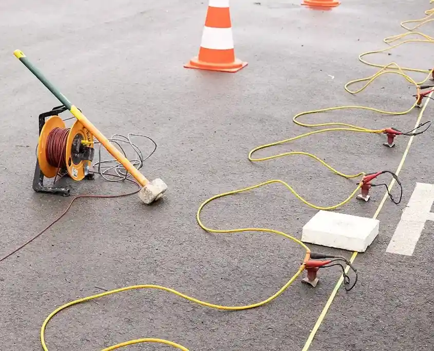
Fieldwork in Memphis often reveals the loess mantle's influence on near-surface velocity gradients. This wind-deposited silt, 20 to 60 feet thick along the bluffs, exhibits P-wave velocities between 400 and 800 m/s in unsaturated conditions but drops sharply when moisture content rises after heavy rainfall. Crews working the Wolf River floodplain encounter saturated alluvium with velocities below 300 m/s, requiring careful geophone coupling and longer spread lengths to achieve adequate signal-to-noise ratios. Our data acquisition uses 48-channel seismographs with 4.5 Hz and 14 Hz geophones deployed in linear arrays of 110 to 230 feet, depending on target depth. Source energy comes from a 16-pound sledgehammer on steel plate for shallow refraction, supplemented by an accelerated weight drop when penetration beyond 100 feet is needed. Processing follows ASTM D5777 guidelines, applying first-break picking, delay-time analysis, and tomographic inversion using ray-tracing algorithms that handle the velocity inversions common in layered embayment sediments. Reflection processing incorporates CDP stacking, NMO correction, and migration routines tuned for the high-frequency content recoverable from shallow targets. For sites near the Mississippi River where fill and alluvium complicate interpretation, we combine seismic tomography with CPT soundings to calibrate velocity-to-strength correlations directly against measured tip resistance and sleeve friction.
Seismic Tomography (Refraction & Reflection) for Site Characterization in Memphis
Technical reference — Memphis

Area-specific notes

In downtown Memphis, built atop Quaternary alluvium adjacent to the Mississippi River, the seismic risk differs fundamentally from that in the loess-bluff neighborhoods of East Memphis and Germantown. Ground motion is amplified by the alluvium at periods between 0.5 and 1.5 seconds, whereas the stiff loess on the bluffs transmits energy efficiently with less amplification but greater short-period content. A site on Union Avenue might exhibit a Vs30 of 220 m/s (Site Class D), while a location four miles east near Poplar Avenue could surpass 350 m/s and qualify as Site Class C—a distinction that alters the design spectral acceleration by 30 to 40 percent under ASCE 7-22. Overlooking these lateral variations or presuming a uniform stratigraphy across the city introduces errors in seismic hazard assessment that then affect foundation design and structural detailing. The depth to the top of the Memphis Sand and the underlying confining unit is determined by reflection tomography; both units affect ground-motion amplification and liquefaction susceptibility in ways that conventional borehole logging alone cannot capture.

Need a geotechnical assessment?

Reply within 24h.

Email: contact@geotechnicalengineering1.org

Standards used


The following standards are applicable: ASTM D5777 (Standard Guide for Using the Seismic Refraction Method), ASTM D4428/D4428M (Standard Test Methods for Crosshole Seismic Testing), ASCE 7-22 (Minimum Design Loads, including Site Classification based on Vs30), IBC 2021 (International Building Code, with seismic provisions referencing ASCE 7), and ASTM D7400 (Standard Test Methods for Downhole Seismic Testing).

Reference parameters

ParameterTypical value
P-wave velocity range (loess, unsaturated)400–800 m/s
P-wave velocity range (saturated alluvium, floodplain)200–400 m/s
Typical geophone spread length (refraction)110–230 ft (34–70 m)
Geophone frequency4.5 Hz / 14 Hz
Source type (shallow)16 lb sledgehammer on steel plate
Source type (deep penetration)Accelerated weight drop (AWD)
Recording channels48-channel seismograph
Standard referenceASTM D5777, ASTM D4428/D4428M

Top questions


How deep can seismic refraction tomography image in Memphis soils?

Employing a 230-foot geophone spread and an accelerated weight drop as the energy source, we consistently image to depths ranging from 80 to 120 feet within the loess and alluvium of Shelby County. To achieve greater penetration—down to 200 feet or more—either the spread length must be extended or multiple shot points employed. Reflection tomography is capable of reaching the Paleozoic bedrock at depths exceeding 800 feet in the western portion of the city, although resolution diminishes as depth increases.

What does a seismic tomography survey cost in the Memphis area?

In Memphis, a typical seismic refraction or reflection survey costs between US$2,430 and US$5,480. Factors influencing the price include spread length, the number of shot points, and whether crosshole or downhole methods are incorporated. Projects that require combined refraction and reflection processing, or surveys conducted in congested urban areas with restricted access, tend to be priced at the higher end of this range.

How does the Mississippi Embayment geology affect seismic velocities?

The stratigraphy of the embayment—characterized by loess overlying the Memphis Sand, which in turn rests on the Flour Island Formation and Paleozoic bedrock—gives rise to velocity inversions in which higher-velocity sand is covered by lower-velocity alluvium or loess. Conventional refraction interpretation, which assumes that velocity increases with depth, is inadequate under these circumstances. Therefore, we employ ray-based tomographic inversion to accurately model the velocity structure.

What is the ASCE 7 site classification workflow using seismic methods?

The average shear-wave velocity in the upper 30 meters (Vs30) is determined using MASW, downhole, or crosshole seismic techniques. This measured velocity classifies the site into one of the ASCE 7-22 Site Classes (A through F). In the Memphis area, the majority of sites fall into Class C or D. However, sites located near the Mississippi River, where very soft alluvium is present, may qualify as Site Class E, necessitating a site-specific ground-motion analysis.

How does seismic tomography complement geotechnical drilling?

Continuous velocity profiles between and beneath boreholes are provided by seismic tomography, addressing the spatial gaps that discrete sampling cannot fill. When these profiles are calibrated against SPT blow counts or CPT tip resistance from a limited number of boreholes, the resulting velocity model extrapolates soil and rock properties across the entire survey line. This approach reduces the number of required borings and enhances the reliability of the ground model.

Location and service area

We serve projects across Memphis and surrounding areas.

View larger map